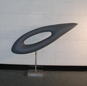
Following figure is the image of the 3D object of interest. Here we assume a metrically calibrated sequence of image. The camera is calibrated by haveing the same planar calibration checkerboard pattern in each image used.
In this experiment, seven images were taken (as shown in following Fig). Among them, three were used for estimating the bottom of the object and four were used for estimating the lower boundery of the hole in the object.
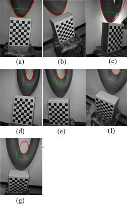
In the figure above, the green polygon is the convex hull of the projected cube boundary. The red courve is the apparent contour of the reconstructed strface. (a) - (c) are used for reconstructing the surface patch in the bottom cube. (d) - (g) are used for reconstructing the surface patch in the cube near the hole.
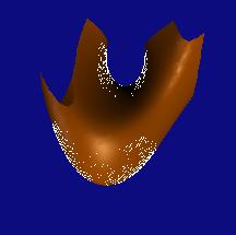
The following figure (a) shows a 4th degree algebraic surface fit to data point sampled from the two quardric surface patches.
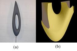
In the following figure, the white pooint are samples from the two estimated quadric patches and were used in estimateing the 4th degree algebraic surface are seen.
Last updated: November 4, 2001
Back to research topics.